By R. Savija
All specifications for electroplating, whether military, federal, ISO, ASTM or SAE-AMS specifications, have an initial section that contains essential information to be supplied by the purchaser to the electroplater. More times than not, much of this information is omitted from part prints and purchasing documents which opens the door to potential miscommunication and finishing shortfalls. This blog details some of the more common omissions that are discovered by Advanced Plating Technologies’ engineering staff during quoting or contract review of specifying a plating process.
Specification of the plating thickness and tolerance requirements:
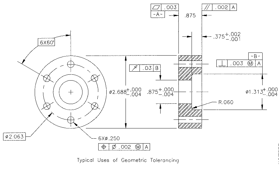 Often a minimum/maximum thickness tolerance without a defined checkpoint cannot be realistically obtained with a traditional electroplating process. For example, a plating specification that lists a minimum plating thickness of 0.0003” and a maximum plating thickness of 0.0005” for all surfaces of an electroplated part would not be achievable on most part geometries due to the inherent variations in electrolytic plating distribution.
Plating thickness varies due to the inconsistent distribution of plating current on an electroplated part. Ionic plating current, like electrical current, takes a preferential path of least resistance with the corners and ends of a part receiving a higher current density and therefore higher plating thickness. If the design of a component requires a very tight plating tolerance, it is important to designate a functional surface where a plating thickness check point can be established. If the plating is specified as 0.0003” minimum and 0.0005” maximum with a specific checkpoint, a plating protocol can generally be developed to consistently meet this requirement. Any specific part dimensional tolerances should be addressed in combination with a plating thickness checkpoint to allow for a combined plating thickness and part dimensional inspection protocol.
Hardness or Strength Requirements
Most electroplating specifications require hydrogen embrittlement relief baking for high strength or hardened steels having a strength greater than 180ksi or Rockwell hardness of 40 HRC or more. In addition, pre-plate stress relief bakes are often required within plating specifications for hardened or cold-worked ferrous materials. Often the hardness of a steel component is not listed on the drawing or purchase order which requires follow up during quoting or contract review. In some cases the hardness of a steel material is not so obvious, such as with music wire used in springs and wire-forms. The purchaser rarely specifies the tensile strength of music wire on the drawing. A closer examination, however of the music wire specifications such as ASTM A228 indicate that all music wire has a tensile strength well above180 ksi which is the strength equivalent of 40 HRc.
Condition of the As-received Material
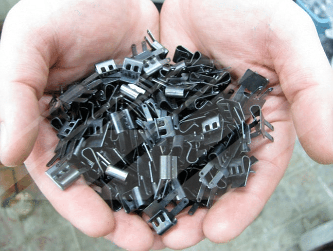 It is not uncommon for a metal finishing facility to receive parts with a heavy oil or heavy heat treat scale. This type of a condition is generally not discussed during the quoting stage nor are there advisories on part prints, specifications or purchasing documents. Excessive oil and heat treatment scale require additional operations to prepare the parts for successful finishing. The additional processes are often “off-line” in that they are a separate process independent from the plating line. Such processes include aggressive chemical descales, vapor degreasing and sand/vapor blasting processes. These steps add additional time/cost that are generally not included in a standard quote. In such cases, further discussion is required to determine the most cost effective way to prepare future orders of parts for plating. Often proper cleaning of parts prior to heat treatment, alternative heat treatment methods such as vacuum heat treating or cleaning prior to heat treatment can ensure parts are received ready-to-plate thereby eliminating additional preparatory steps.
Surface Roughness
It is a common misconception that electroplating can actually cover-up up surface imperfections on the part and that electroplating can significantly improve surface roughness. In most plating applications, this is not the case and it is generally recommended that the pre-plate surface roughness be slightly better than the desired post-plate surface finish. For example, if a post-plate Ra of 16uin is required, it is generally recommended that a pre-plate Ra of 10-12uin be provided. This is especially true of electroless processes such as electroless nickel that have virtually no “leveling” properties.
Plating Buildup on Threads
 It is not uncommon for improper allowance to be made for plating buildup on threads. Since plating builds on two sides of the part and both sides of the thread land, a total of four times the nominal plating thickness should be used as a guide for the increase (male) or decrease (female) in thread pitch. The formula below details the calculation for change in pitch diameter as a function of the plating thickness and included angle (Note: the included angle for most common thread forms is 60-degrees):
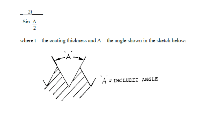 As an example, a 0.0002” plating thickness will cause the pitch diameter of a male thread to increase by a factor of four or 0.0008” for standard 60° UNC or UNF threads. This plating buildup is even further exacerbated on the lead threads of long fasteners or shafts where a localized plating thickness at the lead thread may be as high as four to five times the nominal thickness depending on where the plating thickness checkpoint is established. In such a case, the target plating thickness of 0.0002” may be as high as 0.0008” as measured at the lead thread resulting in as high as 0.0032” increase in thread pitch. In such applications, it is very important to discuss allowances for thread pitch build and define a plating thickness checkpoint to ensure that parts can be successfully plated and meet post-plate gauging requirements.
Racking Locations
 For parts that are rack plated, allowance must be made for contact locations of the rack tips. The rack tips are what physically contact the part to fixture it throughout the plating process. At the rack tip contact points there will nearly always be rack marks and lack of full plating coverage. This is due to the fact that current passes through the rack tips and into the part at the contact points. In addition, plating chemistry/solutions cannot fully wet the surface of the part beneath the rack contact points. Due to the fact that the plating coverage will be incomplete with visible marks at the contact points, it is important that the purchaser convey non-functional or non-critical locations on the drawing where racking is permissible. This is usually a location where the purchaser deems that rack marks are not detrimental to the function or appearance of the part.
The above points detail just a few commonly overlooked areas that are critical to a successful outcome in a metal finishing process. By carefully reviewing the ordering information listed within most plating specifications, the purchaser can be assured that details critical to a successful plating outcome are detailed at time of quote or purchase. Advanced Plating Technologies is happy to provide guidance along these lines by talking with any of our estimating or process engineers. Visit the contact us section of our website to submit a plating inquiry or general question regarding specifying a plating process. Our Technical Library contains common plating topics, specifications and white papers specific to the plating process.