
By James Lindstedt, Manufacturing & Process Engineer
Rack Plating Introduction – A Metal Finishing Job Shop
Advanced Plating Technologies is a metal finishing job shop. What does that mean? A metal finishing job shop encounters the metal finishing demands of any industry that has a need for metal finishing. Metal finishing is a highly diverse industry serves the needs of a myriad of other industries. Although there is always common ground, every industry has its own unique set of needs and criteria for metal finishing. The conscientious metal finisher must be able to recognize these unique requirements, and reconcile them with the nuances of the plating methods and processes.
Rack Plating & Tooling
When quoting at a prospective job, some of the key factors to consider are:
- Part geometry
- End use
- Base material
- Part volume (EAU)
- Throughput
- Type Of Process (Electroless, Electrolytic, Immersion Only, etc)
There is one critical item that unites all of the above bullet points: TOOLING. Tooling is one of the most important inputs when we begin to put together a metal finishing solution. Often times a tooling charge may be incorporated into a quote as an effort to optimize the process at the onset of the job. In the context of metal finishing, tooling is the broad category of hardware that is required to apply the finish to the part. Tankage, bussing, power supplies, HVAC, plating barrels, plating racks, masking, agitation equipment, and material handling equipment can all fall under the umbrella of tooling. Rack plating is a particular area of concern with respect to tooling. Designing an effective plating rack often consumes a large amount of engineering bandwidth during the development of a new job.
Defining Rack Plating
The broad-stroke category of plating that Advanced Plating Technologies performs falls into a category known as “loose piece” plating. This term serves mainly to distinguish from continuous forms of plating, such as reel-to-reel. In loose piece plating, the goal is to apply the desired finish to an individual part – the “loose piece”. The loose pieces are processed as a load of varying degrees of size, using tools called plating barrels or plating racks. As such, when developing the finishing protocol, the finisher must choose a physical means with which to apply the finish to the loose piece. There are two principal subcategories of loose piece plating – barrel plating and rack plating. The first discussion of this two-part blog will cover the latter – rack plating.
Rack plating is a method that involves fixturing individual parts into an array that is mounted on a solid frame – the so-called plating rack. The plating rack serves the following purposes:
- To physically hold the parts in a secure manner
- To maintain electrical contact with and to pass DC current to the parts
- To orient the parts appropriately in accordance with the thickness specifications, part geometry, drainage, gas elimination, and quality requirements.
- To optimize throughput
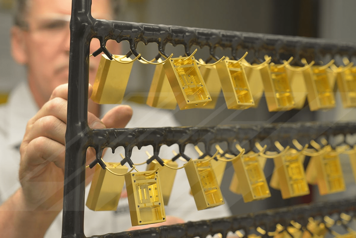
Some representative photos of rack plating and the diversity thereof are shown below:
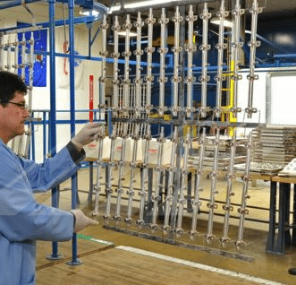 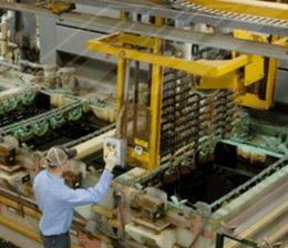  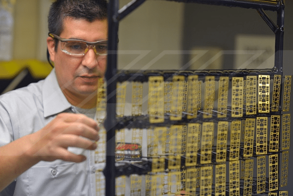 |
Figure 1.1 – Rack Plating Fixtures and Their Diversity
Rack plating can be configured to accommodate virtually any part size or geometry. Racks can be made for a single part, or thousands of parts; a rack may be the size of a textbook, or the size of a garage door. In any case, rack plating requires careful consideration of plating process phenomena and the nuances of the part in question.
The Relationship Between Rack Plating And the Plating Cell
Electroplating is an electrochemical process. Driven by an external DC power source, metal cations, such as Ni2+, are reduced at the surface of the part (the cathode of the plating cell) to nickel metal (Ni0). The anodes in Figure 1.2 are the sources of new metal ions to replace the ions being plated on to the part. This process involves the physical movement of ions through the plating solution at a rate on the order of 0.01 centimeters per second. The rate of ion flow can be manipulated by what is referred to in the industry as current density – that is, the ratio of current supplied by the DC power supply to the surface area of the cathode (i.e., the parts being plated). The importance of current density as a metric in the industry cannot be understated, particularly with regard to rack plating. Current density manipulation is often a principal reason for developing a custom rack.
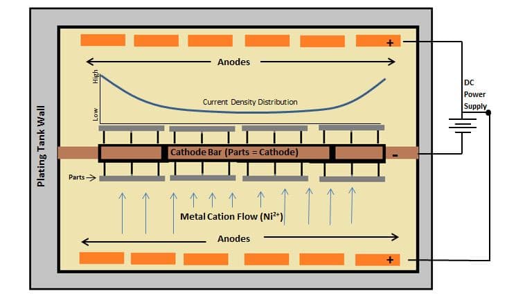
Figure 1.2 – A Schematic Drawing of a Rack Plating Cell (As Viewed From Above; NOT TO SCALE)
For a given array of parts on a plating rack, the current density is not distributed evenly across the parts; almost without exception, there will be a gradient.
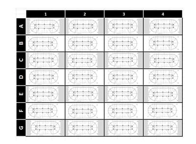
Figure 1.3 – A Schematic Representation Of An Array Of Parts Configured For Rack Plating
Consider Figure 1.3 – a schematic representation a plating rack. As illustrated in Figure 1.2, the parts around the perimeter of the array would be considered “high current density areas”, meaning that they will receive a relatively higher amount of metal deposition than the more interior pieces. So, other things being equal, a piece located at position A1 or G4 would receive a higher amount of plating buildup than a piece located at position D2 or E3.
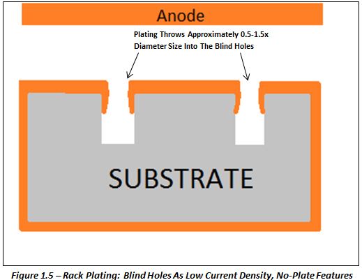
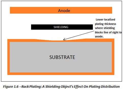
Similarly, the portion of the part that is toward the interior of the plating cell, rather than facing the anodes, will have less plating buildup – this is a phenomena known as “shielding”. Just as a tree may provide shade from the sun, physical objects between the anode and cathode of the plating cell will shield metal deposition. In addition to shielding, a surface that is facing the anodes will have less plating buildup in holes, recesses, cavities, or other internal features. These tendencies can be mitigated through sound rack design. Parts may be oriented on the rack in such a way that critical features are facing the anodes. In more technical applications, a plating rack may even be developed with an auxiliary anode inside of the parts to generate the required current density in a hole or other recessed feature.
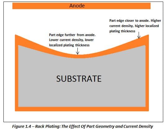
Figures 1.4 through 1.6 are exaggerated rack plating illustrations showing the relationships between part geometry, current density, and plating thickness.
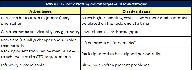
The following table is a summary of the advantages and disadvantages of rack plating:
Conclusion
Rack plating plays a very key role in developing effective metal finishing protocols. It is the responsibility of the conscientious metal finisher to recognize the customers’ needs, and to reconcile them with the often-misunderstood idiosyncrasies of the plating process. When considering the factors that have been discussed above, often the most appropriate method of processing reveals itself. Other times, several iterations of trial and error may come to pass before the solution becomes clear. Regardless, in rack plating it is always advisable to develop a custom tool for the application. This will ensure that the process is optimized and parts are being processed in a manner that in consistent with good plating practice. Advanced Plating Technologies has vast experience in designing in building plating racks. A staff of Manufacturing and Process Engineers work directly with customers from the quoting phase all the way through to full scale production. This ensures that the unique needs of the job are being met from a tooling and processing standpoint, which is particularly important when custom racks are required for a job. Additionally, the APT engineers have a well-established relationship with local rack fabricators to facilitate sound rack design, rapid rack prototyping and scaling into production.